

This comprehensive guide covers everything you need to know about waterproof coaxial cables—from understanding water...
Coaxial Cable Impedance: The Complete Guide (50Ω vs 75Ω)
Coaxial Cable Impedance: The Complete Guide
Published by Wassalat Technical Team
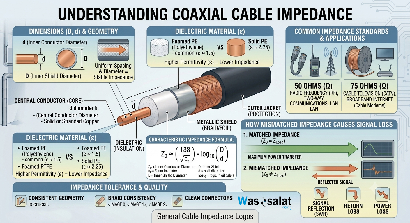
Impedance is arguably the most important electrical property of a coaxial cable. Yet, it's also one of the most misunderstood concepts in cabling.
This comprehensive guide explains what impedance is, why it matters, how it's determined, and why matching impedance is critical for signal quality. Whether you're a professional installer or a DIY enthusiast, understanding impedance will help you make better cable choices.
? Table of Contents
What Is Impedance?
Impedance is the measure of opposition that a cable presents to the flow of alternating current (AC). In simple terms, it's like the "electrical resistance" of the cable, but for AC signals rather than DC.
Unlike resistance (which is constant), impedance depends on frequency. A cable might have an impedance of 50Ω at 100 MHz, but that same cable would have a different impedance at 1 GHz.
Impedance vs Resistance
| Property | Resistance | Impedance |
|---|---|---|
| Definition | Opposition to DC current | Opposition to AC current |
| Frequency Dependent | No | Yes |
| Symbol | R | Z |
| Unit | Ohms (Ω) | Ohms (Ω) |
| Components | Pure resistance | Resistance + Reactance |
? Simple Analogy: Think of impedance like the width of a pipe. A 50Ω pipe is one size, a 75Ω pipe is another. If you connect the wrong size pipe, water (the signal) will splash back (reflections) and you'll lose pressure (signal strength).
Why Impedance Matters
Impedance matters because it determines how efficiently signals are transferred from one device to another through the cable.
Three Key Reasons
1. Maximum Power Transfer
Maximum power is transferred when the source impedance equals the load impedance. This is called "impedance matching." If the impedances don't match, some power is reflected back rather than delivered to the load.
2. Signal Integrity
Mismatched impedance causes signal reflections that distort the original signal. This results in:
- Ghosting in video
- Errors in data
- Distortion in audio
- Reduced range in wireless systems
3. Equipment Protection
In high-power applications, reflected signals can damage transmitters. A mismatched antenna feed can cause a transmitter to overheat and fail.
⚠️ Warning: Using the wrong impedance cable can cause equipment damage, not just poor performance. Always match your cable to your equipment's impedance!
How Impedance Is Determined
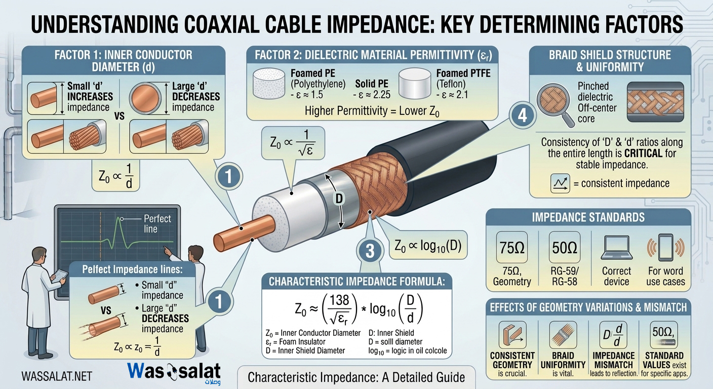
A coaxial cable's impedance is determined by three physical factors:
The Formula
Z = (138 × log₁₀(D/d)) ÷ √(εᵣ)
Where:
- Z = Impedance (in Ohms)
- D = Inner diameter of the shield (mm or inches)
- d = Diameter of the center conductor (mm or inches)
- εᵣ = Dielectric constant (relative permittivity)
The Three Factors Explained
| Factor | Effect on Impedance | Real-World Impact |
|---|---|---|
| Center Conductor (d) | Smaller conductor = Higher impedance | RG-59 (22 AWG) is 75Ω; RG-58 (20 AWG) is 50Ω |
| Shield Diameter (D) | Larger shield = Lower impedance | RG-6 (6.9mm) vs RG-11 (10.3mm) – both 75Ω |
| Dielectric Constant (εᵣ) | Higher constant = Lower impedance | Air (1.0) vs PE (2.26) – air gives higher impedance |
Visual Representation
The Standards: 50Ω vs 75Ω
There are two primary impedance standards for coaxial cables: 50Ω and 75Ω.
50Ω – The RF Standard
Why 50Ω?
50Ω represents the optimal balance between:
- Power handling – Maximum power transfer occurs at 50Ω
- Signal loss – Minimum attenuation occurs at 50Ω
Applications:
- Two-way radios
- WiFi and wireless networks
- Amateur radio
- RF test equipment
- LTE and 5G base stations
- Antenna feeds
Common 50Ω Cables:
- RG-58, RG-8, RG-213
- LMR-195, LMR-240, LMR-400, LMR-600
- Belden 9913, 9914
75Ω – The Video Standard
Why 75Ω?
75Ω offers the lowest possible signal loss for a given cable size. This makes it ideal for:
- Long-distance video transmission
- High-bandwidth data
- Broadcast applications
Applications:
- Cable TV (CATV)
- Satellite TV
- CCTV and surveillance
- Broadcast video
- Digital audio
Common 75Ω Cables:
- RG-6, RG-11, RG-59
- Belden 1694A, 1505A
- High-density plenum cables
✅ Quick Reference:
- 50Ω = RF, Radio, Wireless
- 75Ω = Video, CATV, CCTV
- Never mix them without proper impedance matching!
What Happens When Impedance Mismatches?
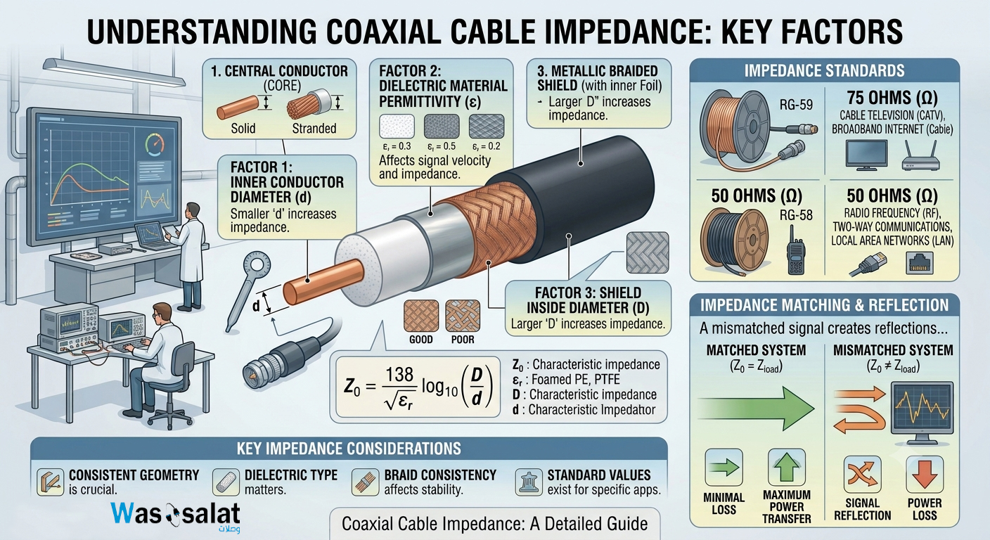
When you connect a 50Ω cable to a 75Ω device (or vice versa), you create an impedance mismatch.
The Effects
1. Signal Reflections
At the point where the impedances change, some of the signal is reflected back toward the source. This reflected signal:
- Reduces the power reaching the destination
- Interferes with the forward signal
- Creates standing waves
2. Signal Loss
The reflected signal means less signal reaches the destination. The loss from a direct 50Ω to 75Ω mismatch is about:
- 0.18 dB (about 4% power loss)
- This may not sound like much, but in long runs, it adds up
3. Standing Wave Ratio (SWR)
SWR measures how much power is reflected. A perfect match is 1:1. A 50Ω/75Ω mismatch gives about 1.5:1 SWR.
4. Equipment Damage
In high-power applications (radio transmitters), reflected power can:
- Overheat the transmitter
- Reduce transmitter lifespan
- Cause premature failure
Visual Example
| Scenario | SWR | Power Loss | Signal Impact |
|---|---|---|---|
| Perfect Match (50Ω→50Ω) | 1:1 | 0% | Optimal |
| Mild Mismatch (50Ω→60Ω) | 1.2:1 | 0.8% | Negligible |
| Standard Mismatch (50Ω→75Ω) | 1.5:1 | 4% | Noticeable |
| Severe Mismatch (50Ω→100Ω) | 2:1 | 11% | Significant |
How to Measure Impedance
Measuring cable impedance requires specialized equipment. Here are the methods:
1. Time Domain Reflectometry (TDR)
What it is: Sends a pulse down the cable and measures reflections
Accuracy: Very high
Cost: High ($1,000+)
Common Use: Professional installations, troubleshooting
2. Vector Network Analyzer (VNA)
What it is: Measures S-parameters to calculate impedance
Accuracy: Extremely high
Cost: Very high ($5,000+)
Common Use: Lab testing, manufacturing
3. Impedance Bridge
What it is: Compares cable to known standards
Accuracy: High
Cost: Moderate ($500-$2,000)
Common Use: Professional testing
4. Cable Tester (Simple)
What it is: Continuity and basic impedance check
Accuracy: Low to moderate
Cost: Low ($50-$200)
Common Use: Quick field checks
5. Multimeter (Not Recommended!)
What it is: Measures DC resistance only
Accuracy: Not applicable (doesn't measure impedance)
Cost: Low ($20-$100)
Common Use: NOT for impedance measurement
⚠️ Important: A multimeter measures resistance, not impedance. You CANNOT measure cable impedance with a standard multimeter.
Connector Impedance
Connectors have their own impedance ratings and are NOT interchangeable between 50Ω and 75Ω systems.
50Ω Connectors
| Connector | Impedance | Common Use |
|---|---|---|
| N-Type | 50Ω | Outdoor RF, WISP, Cellular |
| SMA | 50Ω | WiFi, IoT, Test Equipment |
| BNC (50Ω) | 50Ω | Test equipment, Radios |
| TNC | 50Ω | Military, Aerospace |
75Ω Connectors
| Connector | Impedance | Common Use |
|---|---|---|
| F-Type | 75Ω | CATV, Satellite, Broadband |
| BNC (75Ω) | 75Ω | Video, Broadcast, CCTV |
| RCA | 75Ω | Consumer Video/Audio |
? Remember: 50Ω BNC connectors have a larger center pin than 75Ω BNC connectors. They are not interchangeable!
Impedance Adapters and Transformers
Sometimes you must connect 50Ω and 75Ω equipment. In these cases, you need an impedance adapter or transformer.
Types of Adapters
1. Impedance Matching Transformer (Balun)
What it does: Converts impedance from 50Ω to 75Ω or vice versa
Loss: Adds 0.5-1.5 dB of loss
Cost: $10-$50
Use: When you must connect mismatched equipment
2. Tapered Adapter
What it does: Gradually transitions from 50Ω to 75Ω
Loss: Lower than balun (0.3-1.0 dB)
Cost: $20-$100
Use: Professional applications requiring less loss
Should You Use Adapters?
| Scenario | Recommended | Alternative |
|---|---|---|
| Connecting 50Ω cable to 75Ω TV | ❌ No | Use 75Ω cable instead |
| Connecting 75Ω cable to 50Ω radio | ❌ No | Use 50Ω cable instead |
| Testing 50Ω device with 75Ω test equipment | ⚠️ Maybe | Use adapter and account for loss |
| Professional broadcast installation | ✅ Yes (with quality balun) | Re-cable with correct impedance |
⚠️ Best Practice: Avoid adapters whenever possible. It's always better to use the correct impedance cable throughout your entire system.
Impedance Calculation Formula
For those who want to go deeper, here's the full formula:
The Full Formula
Z₀ = √(L/C) = (138 / √εᵣ) × log₁₀(D/d)
Where:
- Z₀ = Characteristic impedance (in Ohms)
- L = Inductance per unit length
- C = Capacitance per unit length
- εᵣ = Relative permittivity (dielectric constant)
- D = Inner diameter of the shield
- d = Diameter of the center conductor
Example Calculation: RG-6
| Parameter | Value |
|---|---|
| D (Shield ID) | 4.57 mm |
| d (Conductor OD) | 1.02 mm (18 AWG) |
| D/d Ratio | 4.48 |
| log₁₀(D/d) | 0.651 |
| εᵣ (Foam PE) | 1.5 |
| √εᵣ | 1.22 |
| 138 / 1.22 | 113.1 |
| Z₀ | 73.6 Ω (≈75Ω) |
Common Impedance Values
While 50Ω and 75Ω are the most common, other impedances exist:
| Impedance | Common Use | Example Cables |
|---|---|---|
| 50Ω | RF, Radio, Wireless | RG-58, RG-8, LMR-400 |
| 75Ω | Video, CATV, Broadcast | RG-6, RG-11, RG-59 |
| 93Ω | Older Digital Systems | RG-62 (ARCnet, IBM) |
| 100Ω | Ethernet (Twisted Pair) | Cat5e, Cat6 (not coax) |
| 300Ω | Old TV Antennas | Twin-lead (not coax) |
| 600Ω | Telephone / Audio | Bell System (historical) |
Frequently Asked Questions (FAQ)
1. What is cable impedance?
Impedance is the opposition a cable presents to AC current. It's the ratio of voltage to current, measured in ohms (Ω). Coaxial cables are typically 50Ω or 75Ω.
2. Why are there different impedances?
50Ω offers the best balance of power handling and low loss for RF applications. 75Ω offers minimum signal loss for video and broadband applications.
3. What happens if I use the wrong impedance cable?
You'll get signal reflections, loss, and poor performance. In high-power applications, you can damage equipment.
4. Can I measure impedance with a multimeter?
No. A multimeter measures DC resistance, which is different from AC impedance. You need specialized equipment like a TDR or VNA.
5. What is characteristic impedance?
Characteristic impedance (Z₀) is the impedance that a cable presents to a signal. It's determined by the cable's physical construction and remains constant regardless of cable length.
6. Is RG-6 50Ω or 75Ω?
RG-6 is 75Ω. It's designed for video and CATV applications.
7. Is LMR-400 50Ω or 75Ω?
LMR-400 is 50Ω. It's designed for RF and wireless applications.
8. Can I use a 75Ω cable with a 50Ω antenna?
You can, but you'll lose about 4% of the signal (0.18 dB). It's not recommended for professional installations.
9. What is VSWR?
VSWR (Voltage Standing Wave Ratio) measures the amount of reflected power in a system. A perfect match is 1:1. Higher numbers mean more reflection.
10. What is a balun?
A balun (balanced-unbalanced) is a device that matches impedance between different systems, like 50Ω to 75Ω. It also balances/unbalances signals.
11. Does cable length affect impedance?
No. Characteristic impedance is independent of cable length. A 1-foot cable of RG-6 has the same impedance as a 1000-foot cable of RG-6.
12. How can I tell if my cable is 50Ω or 75Ω?
Check the markings on the cable jacket. If there are no markings, measure the conductor diameter and shield diameter, then calculate or look up the type.
? Related Articles
- Complete Guide to Coaxial Cables
- What Is a Coaxial Cable?
- 50 Ohm vs 75 Ohm Coax
- Coaxial Cable Construction
- RG6 vs RG11
- RG58 vs RG59
- Browse Coaxial Cables →
? Need the Right Coaxial Cable?
We stock professional coaxial cables in both 50Ω and 75Ω impedances. Whether you need RG-6 for video or LMR-400 for wireless, we have the right cable for your application.
Last Updated: July 2026
© 2026 Wassalat. All rights reserved.
Posted in:
Coaxial Cables
Related posts
-
 Complete Guide to Coaxial Cables
Everything you need to know about RG-6, LMR-400, impedance, connectors & troubleshooting.Read more
Complete Guide to Coaxial Cables
Everything you need to know about RG-6, LMR-400, impedance, connectors & troubleshooting.Read more -
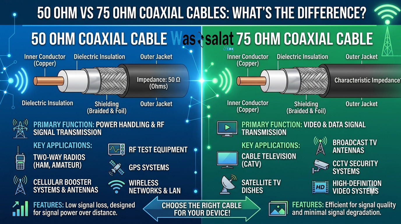 50 Ohm vs 75 Ohm Coaxial Cables: What's the Difference?
Learn the key differences between 50Ω and 75Ω coaxial cables. Find out which impedance you need for WiFi, TV, CCTV,...Read more
50 Ohm vs 75 Ohm Coaxial Cables: What's the Difference?
Learn the key differences between 50Ω and 75Ω coaxial cables. Find out which impedance you need for WiFi, TV, CCTV,...Read more -
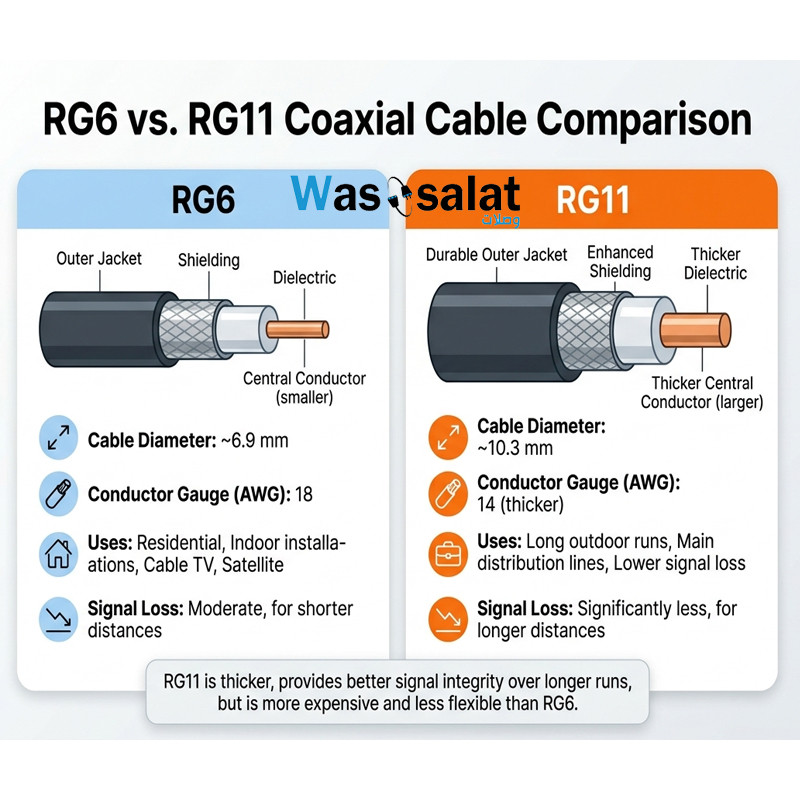 RG6 vs RG11 Coaxial Cables: Which One Do You Need?
Compare RG6 and RG11 coaxial cables. Learn the differences in performance, distance, cost, and when to use each for...Read more
RG6 vs RG11 Coaxial Cables: Which One Do You Need?
Compare RG6 and RG11 coaxial cables. Learn the differences in performance, distance, cost, and when to use each for...Read more -
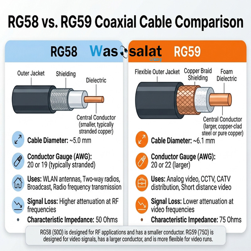 RG58 vs RG59 Coaxial Cables: What's the Difference?
Compare RG58 and RG59 coaxial cables. Learn the critical impedance difference, applications for RF vs video, and...Read more
RG58 vs RG59 Coaxial Cables: What's the Difference?
Compare RG58 and RG59 coaxial cables. Learn the critical impedance difference, applications for RF vs video, and...Read more -
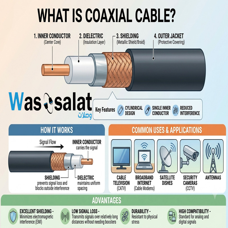 What Is a Coaxial Cable? The Complete Beginner's Guide
Learn what coaxial cables are, how they work, their construction, types, and applications. The beginner's guide to...Read more
What Is a Coaxial Cable? The Complete Beginner's Guide
Learn what coaxial cables are, how they work, their construction, types, and applications. The beginner's guide to...Read more
Latest posts
-
 Waterproof Coaxial Cable: The Complete GuideRead more
 -
 Testing Coaxial Cable: The Complete GuideRead more
This comprehensive guide covers everything you need to know about testing coaxial cable—from simple continuity checks...
-
 Corrugated Coaxial Cable vs Shielded Coaxial Cable: Complete ComparisonRead more
This comprehensive guide compares both technologies—explaining the differences in construction, performance,...
-
 Installing Coaxial Cable: The Complete GuideRead more
This comprehensive guide compares double shield and quad shield coaxial cables—explaining the differences in...
-
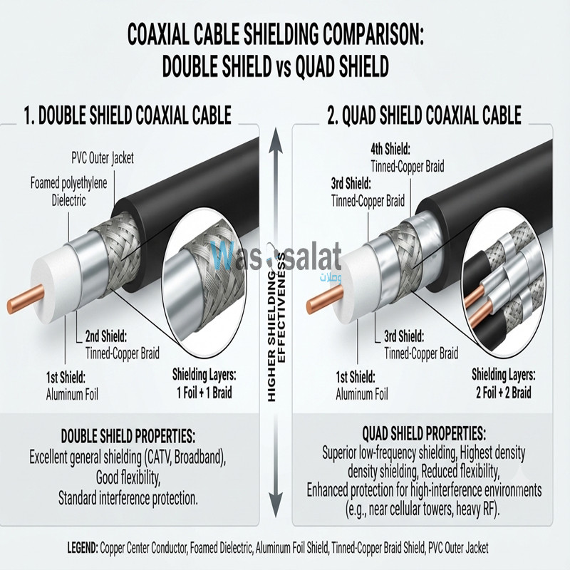 Double Shield vs Quad Shield: Which Coaxial Cable Should You Choose?Read more
This comprehensive guide compares double shield and quad shield coaxial cables—explaining the differences in...
-
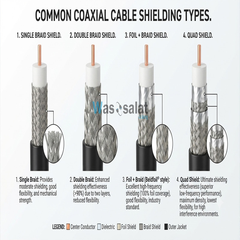 Shielding Types in Coaxial Cables: Complete GuideRead more
This comprehensive guide explains everything you need to know about shielding types—from single shield to quad...
-
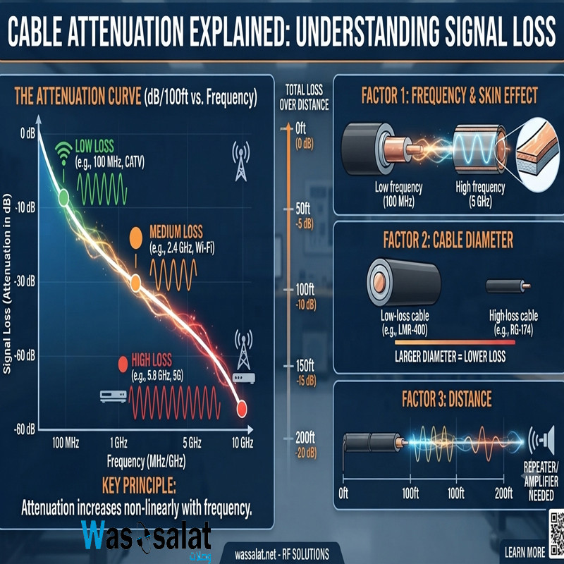 Cable Attenuation Explained: Understanding Signal LossRead more
This comprehensive guide explains everything you need to know about cable attenuation—what it is, what causes it, how...
-
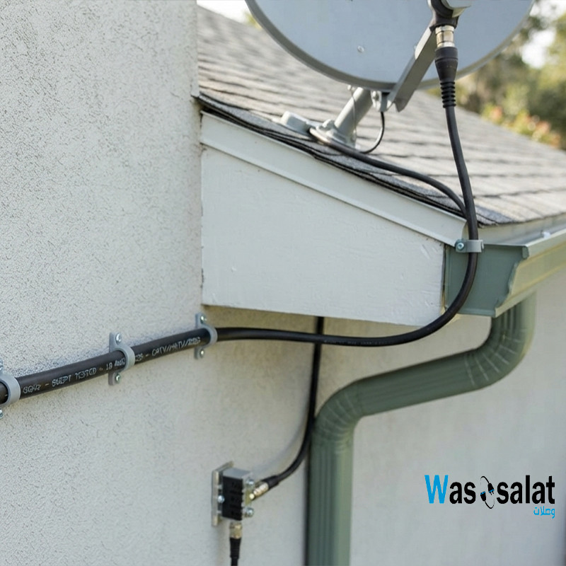 Outdoor Coaxial Cable: Complete Guide & Selection TipsRead more
Choose the right outdoor coaxial cable for your installation. Compare TZC-500/32 vs TZC-500/97, learn about PE...
-
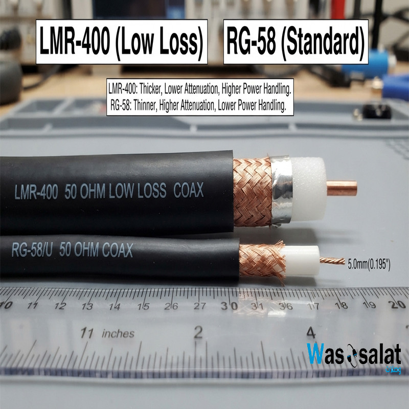 LMR-400 vs RG58: Which Coaxial Cable Should You Choose?Read more
Compare LMR-400 vs RG58 coaxial cables. Learn the differences in signal loss, construction, flexibility, and...
-
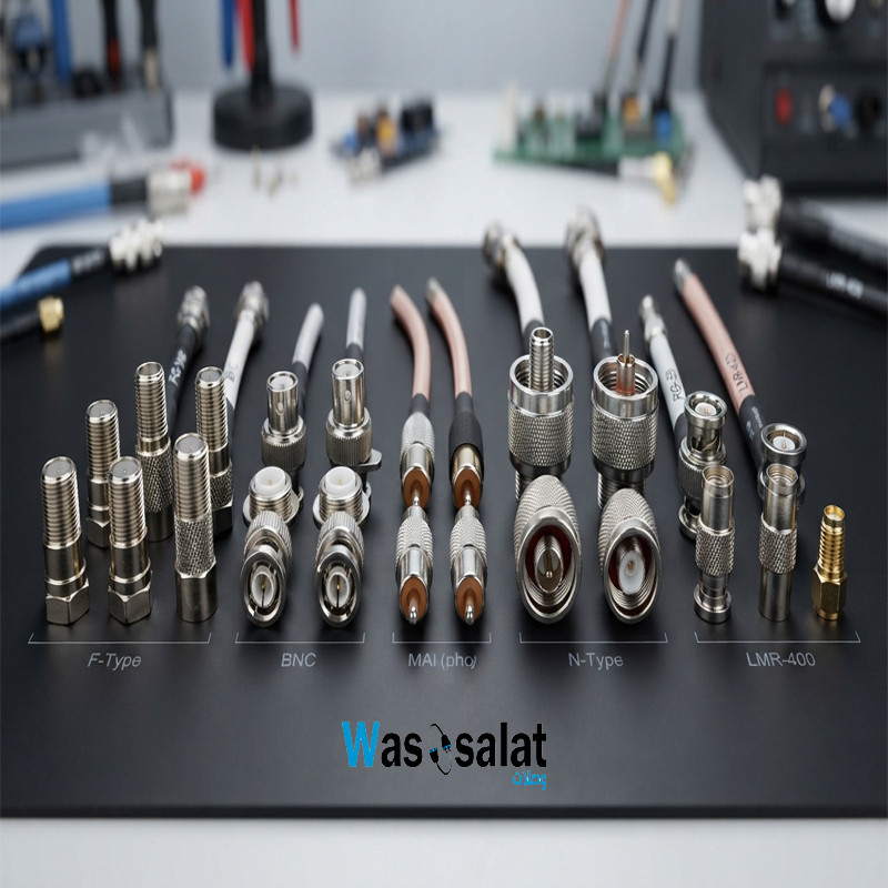 Coax Cable Connectors: Complete Guide to F-Type, BNC, N-Type, SMARead more
Learn about coaxial cable connectors—F-Type, BNC, N-Type, SMA, TNC, and UHF. Compare impedances, frequencies, and...
Leave a comment