

This comprehensive guide covers everything you need to know about waterproof coaxial cables—from understanding water...
Cable Attenuation Explained: Understanding Signal Loss
Cable Attenuation Explained: Understanding Signal Loss
Published by Wassalat Technical Team
Have you ever wondered why your WiFi signal is weak at the end of a long cable run? Or why your TV picture pixelates when you use a long coax cable? The answer is attenuation.
This comprehensive guide explains everything you need to know about cable attenuation—what it is, what causes it, how to measure it, and how to minimize it in your installations.

? Table of Contents
What Is Attenuation?
Attenuation is the gradual loss of signal strength as it travels through a cable. It's the natural reduction in power that occurs when a signal travels over distance.
Think of it like water flowing through a pipe—the longer the pipe, the less water pressure at the end. Similarly, the longer the cable, the weaker the signal at the receiving end.
Attenuation in Simple Terms
- ? Signal goes in – Full strength at the source
- ? Signal travels – Loses energy along the way
- ? Signal comes out – Weaker at the destination
? Key Insight: Attenuation is measured in decibels (dB). Every 3 dB of loss means the signal loses half its power. Every 10 dB of loss means the signal loses 90% of its power.
What Causes Attenuation?
Attenuation is caused by several physical factors:
1. Conductor Resistance
The center conductor has resistance. As the signal travels, some energy is lost as heat. Thicker conductors (like 14 AWG in RG11) have less resistance and therefore less attenuation than thinner conductors (like 22 AWG in RG59).
2. Dielectric Loss
The insulating material (dielectric) absorbs some of the signal energy. Foam dielectric (used in RG6 and LMR cables) has lower loss than solid dielectric (used in RG58 and RG59).
3. Skin Effect
At high frequencies, signals travel on the surface of the conductor rather than through the entire wire. This effectively reduces the conductor's cross-sectional area, increasing resistance and attenuation.
4. Leakage
Some signal energy escapes through the shield. Cables with better shielding (triple or quad shield) have less leakage and therefore less attenuation.
5. Reflections
When impedance is mismatched (e.g., using a 50Ω cable with a 75Ω device), some signal reflects back. This reduces the forward signal and causes attenuation.
How Is Attenuation Measured?
Attenuation is measured in decibels (dB) per unit length, typically per 100 feet or per 100 meters.
Understanding Decibels
| Loss (dB) | Power Loss | Signal Remaining |
|---|---|---|
| 0 dB | 0% | 100% |
| 1 dB | 21% | 79% |
| 3 dB | 50% | 50% |
| 6 dB | 75% | 25% |
| 10 dB | 90% | 10% |
| 20 dB | 99% | 1% |
Measurement Equipment
- Spectrum Analyzer – Professional instrument for measuring signal loss
- Vector Network Analyzer (VNA) – Measures loss and reflection
- Cable Tester – Basic loss measurement for field use
- Signal Meter – Common in satellite and TV installations
Frequency vs Attenuation
Higher frequencies experience more attenuation than lower frequencies. This is why cable selection is critical for high-frequency applications like satellite TV, WiFi, and 5G.
Example: RG6 Attenuation
| Frequency | Application | RG6 Loss (per 100 ft) |
|---|---|---|
| 50 MHz | TV (Low Band) | 1.8 dB |
| 100 MHz | FM Radio | 2.5 dB |
| 400 MHz | UHF TV | 5.2 dB |
| 900 MHz | Cellular | 8.0 dB |
| 1 GHz | SAT TV | 8.5 dB |
| 2.4 GHz | WiFi | 13.5 dB |
⚠️ Note: At 2.4 GHz (WiFi), a 100-foot run of RG6 loses 13.5 dB of signal—that's over 95% of the original signal power! This is why low-loss cables like LMR-400 are essential for WiFi antenna feeds.
Attenuation by Cable Type
Different cable types have different attenuation characteristics:
75Ω Cables (Video/TV)
| Cable | @ 100 MHz | @ 400 MHz | @ 1 GHz |
|---|---|---|---|
| RG59 | 4.6 dB | 9.2 dB | 15.0 dB |
| RG6 | 2.5 dB | 5.2 dB | 8.5 dB |
| RG11 | 1.6 dB | 3.3 dB | 5.4 dB |
50Ω Cables (RF/Radio)
| Cable | @ 100 MHz | @ 400 MHz | @ 1 GHz |
|---|---|---|---|
| RG58 | 4.5 dB | 9.0 dB | 15.0 dB |
| LMR-240 | 2.5 dB | 5.1 dB | 8.4 dB |
| LMR-400 | 1.5 dB | 3.0 dB | 5.0 dB |
| LMR-600 | 1.0 dB | 2.0 dB | 3.3 dB |
Cable Length vs Attenuation
Attenuation is directly proportional to cable length. Double the length = double the loss.
Example: LMR-400 at 900 MHz
| Length | Loss (dB) | Signal Remaining |
|---|---|---|
| 10 ft | 0.4 dB | 91% |
| 25 ft | 1.0 dB | 79% |
| 50 ft | 2.0 dB | 63% |
| 100 ft | 3.9 dB | 41% |
| 150 ft | 5.9 dB | 25% |
| 200 ft | 7.8 dB | 17% |
Connector Loss
Each connector in a cable system adds additional attenuation. Here are typical losses:
| Connector Type | Typical Loss | Notes |
|---|---|---|
| F-Type Compression | 0.1 dB | Best for TV/Satellite |
| F-Type Screw-On | 0.3-0.5 dB | Not recommended |
| BNC | 0.1-0.2 dB | Professional standard |
| N-Type | 0.05-0.1 dB | Best for RF |
| SMA | 0.1-0.2 dB | Common for WiFi |
| Barrel/Adapter | 0.2-0.5 dB | Avoid when possible |
⚠️ Important: Every connector adds loss. In a typical installation with multiple connectors, splitters, and adapters, connector loss can easily add up to 3-6 dB—significantly reducing signal quality.
How to Minimize Attenuation
1. Choose the Right Cable
Use low-loss cables like LMR-400 or RG6 instead of RG58 or RG59, especially for long runs or high frequencies.
2. Keep Cable Runs Short
Plan your installation to minimize cable length. Every foot of cable adds loss.
3. Use Quality Connectors
Use compression or crimp connectors instead of screw-on connectors. They have lower loss and better reliability.
4. Minimize Connectors
Use as few connectors as possible. Avoid barrel connectors and adapters when you can use a continuous cable.
5. Use Amplifiers (When Necessary)
For long runs, use signal amplifiers to compensate for cable loss. Place them at the source, not the destination.
6. Match Impedance
Ensure all cables, connectors, and equipment match impedance (50Ω or 75Ω). Impedance mismatches cause reflections and additional loss.
7. Use Larger Cables for Long Runs
For runs over 200 feet, consider upgrading from RG6 to RG11 or from LMR-400 to LMR-600.
Frequently Asked Questions (FAQ)
1. What is cable attenuation?
Attenuation is the loss of signal strength as it travels through a cable. It's measured in decibels (dB) per unit length.
2. What causes attenuation?
Attenuation is caused by conductor resistance, dielectric loss, skin effect, leakage, and impedance mismatches.
3. Does frequency affect attenuation?
Yes. Higher frequencies experience more attenuation than lower frequencies. This is why low-loss cables are essential for WiFi and satellite TV.
4. What is the acceptable attenuation for a cable?
It depends on the application. For TV, total loss under 10 dB is acceptable. For WiFi, total loss under 5 dB is recommended for optimal performance.
5. How can I reduce attenuation?
Use lower-loss cables, keep cable runs short, use quality connectors, minimize connectors, and match impedance.
6. How much attenuation does a connector add?
Typically 0.1-0.5 dB per connector, depending on the type and quality.
7. What is the difference between loss and attenuation?
They are often used interchangeably. Attenuation is the generic term for signal loss. Loss typically refers to the total attenuation in a system.
8. How do I measure attenuation?
Use a spectrum analyzer, vector network analyzer (VNA), cable tester, or signal meter.
9. What is a "good" attenuation value?
Lower is better. For a 100-foot run, attenuation under 5 dB at 100 MHz is considered good.
10. Does attenuation affect internet speed?
Yes. High attenuation in your coax cable can reduce broadband internet speeds and cause connection issues.
? Related Articles
- Complete Guide to Coaxial Cables
- LMR-400 vs RG58
- RG6 vs RG11
- Coaxial Cable Impedance
- Best Coax Cable for WiFi
? Need Low-Loss Coaxial Cables?
We stock professional low-loss cables including LMR-400, LMR-600, RG6, and RG11. Reduce signal loss and improve performance with quality cables.
Last Updated: July 2026
© 2026 Wassalat. All rights reserved.
Posted in:
Coaxial Cables
Related posts
-
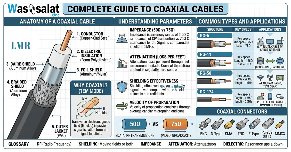 Complete Guide to Coaxial Cables
Everything you need to know about RG-6, LMR-400, impedance, connectors & troubleshooting.Read more
Complete Guide to Coaxial Cables
Everything you need to know about RG-6, LMR-400, impedance, connectors & troubleshooting.Read more -
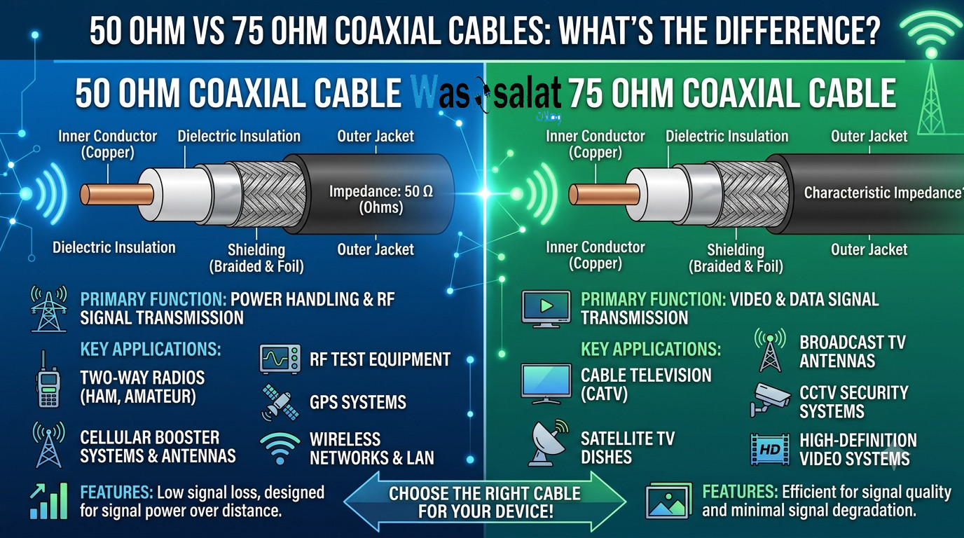 50 Ohm vs 75 Ohm Coaxial Cables: What's the Difference?
Learn the key differences between 50Ω and 75Ω coaxial cables. Find out which impedance you need for WiFi, TV, CCTV,...Read more
50 Ohm vs 75 Ohm Coaxial Cables: What's the Difference?
Learn the key differences between 50Ω and 75Ω coaxial cables. Find out which impedance you need for WiFi, TV, CCTV,...Read more -
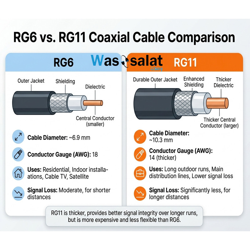 RG6 vs RG11 Coaxial Cables: Which One Do You Need?
Compare RG6 and RG11 coaxial cables. Learn the differences in performance, distance, cost, and when to use each for...Read more
RG6 vs RG11 Coaxial Cables: Which One Do You Need?
Compare RG6 and RG11 coaxial cables. Learn the differences in performance, distance, cost, and when to use each for...Read more -
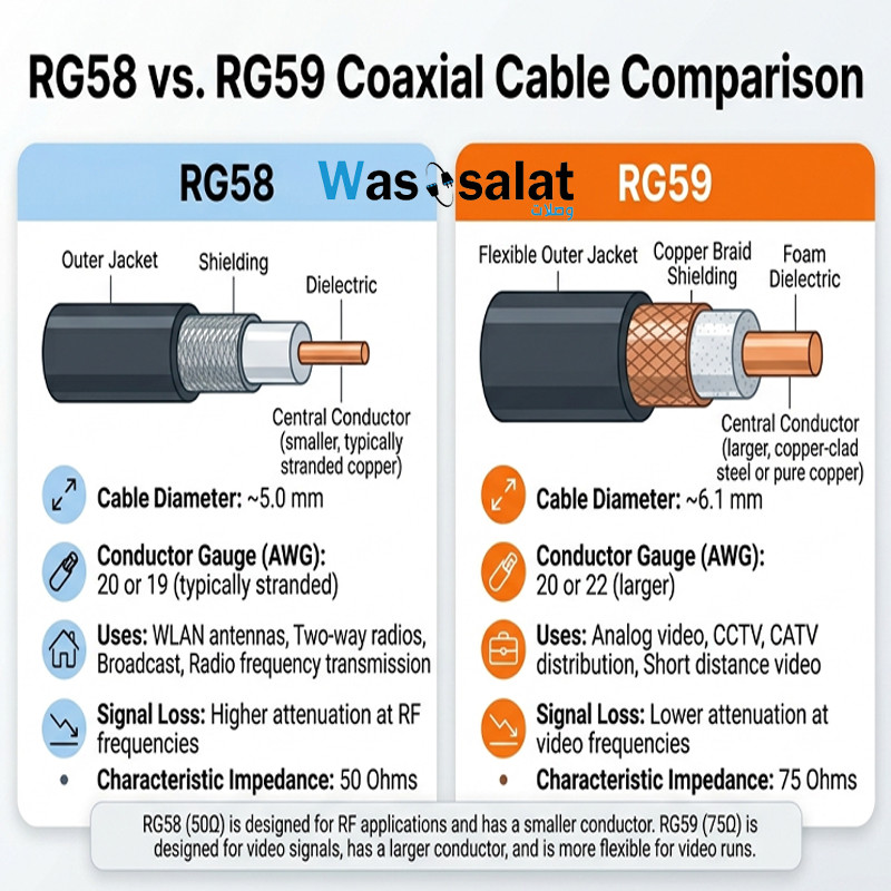 RG58 vs RG59 Coaxial Cables: What's the Difference?
Compare RG58 and RG59 coaxial cables. Learn the critical impedance difference, applications for RF vs video, and...Read more
RG58 vs RG59 Coaxial Cables: What's the Difference?
Compare RG58 and RG59 coaxial cables. Learn the critical impedance difference, applications for RF vs video, and...Read more -
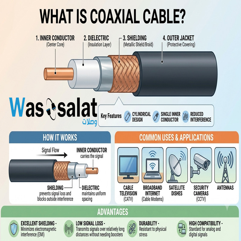 What Is a Coaxial Cable? The Complete Beginner's Guide
Learn what coaxial cables are, how they work, their construction, types, and applications. The beginner's guide to...Read more
What Is a Coaxial Cable? The Complete Beginner's Guide
Learn what coaxial cables are, how they work, their construction, types, and applications. The beginner's guide to...Read more
Latest posts
-
 Waterproof Coaxial Cable: The Complete GuideRead more
 -
 Testing Coaxial Cable: The Complete GuideRead more
This comprehensive guide covers everything you need to know about testing coaxial cable—from simple continuity checks...
-
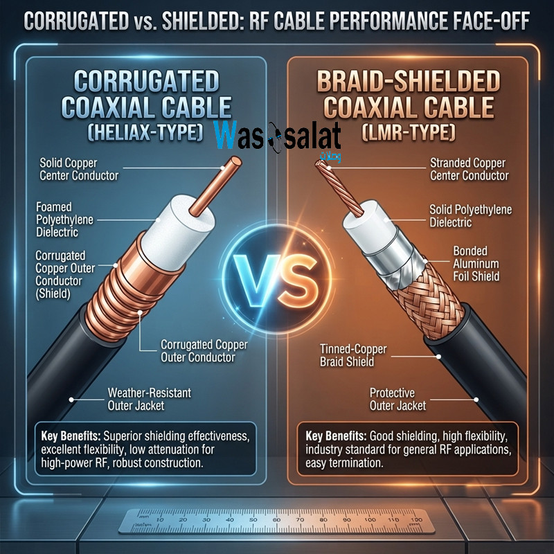 Corrugated Coaxial Cable vs Shielded Coaxial Cable: Complete ComparisonRead more
This comprehensive guide compares both technologies—explaining the differences in construction, performance,...
-
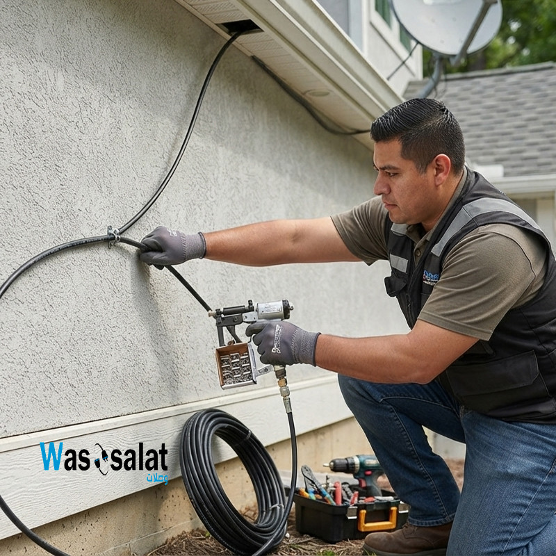 Installing Coaxial Cable: The Complete GuideRead more
This comprehensive guide compares double shield and quad shield coaxial cables—explaining the differences in...
-
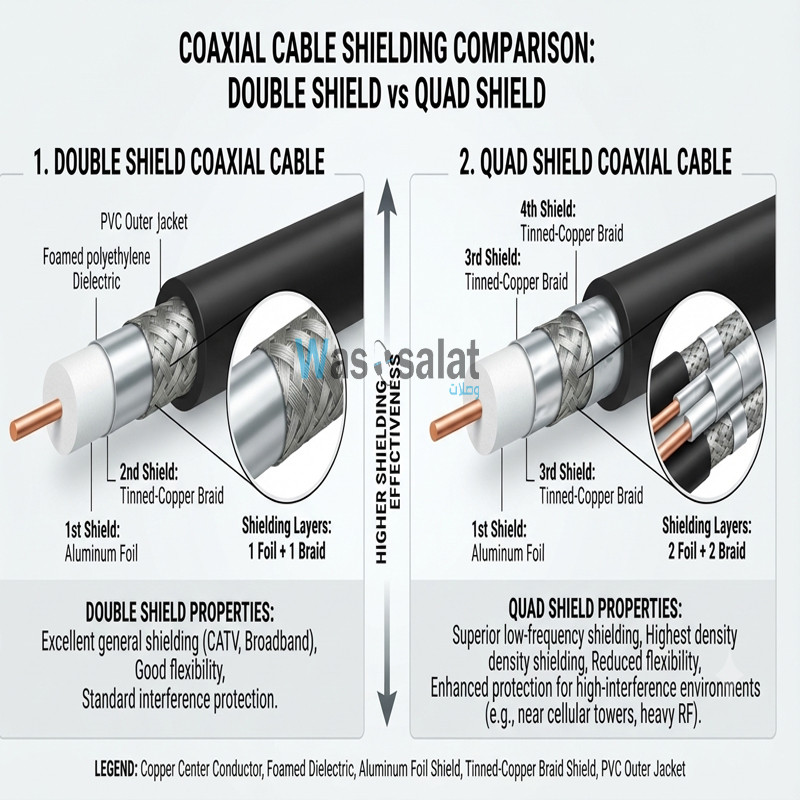 Double Shield vs Quad Shield: Which Coaxial Cable Should You Choose?Read more
This comprehensive guide compares double shield and quad shield coaxial cables—explaining the differences in...
-
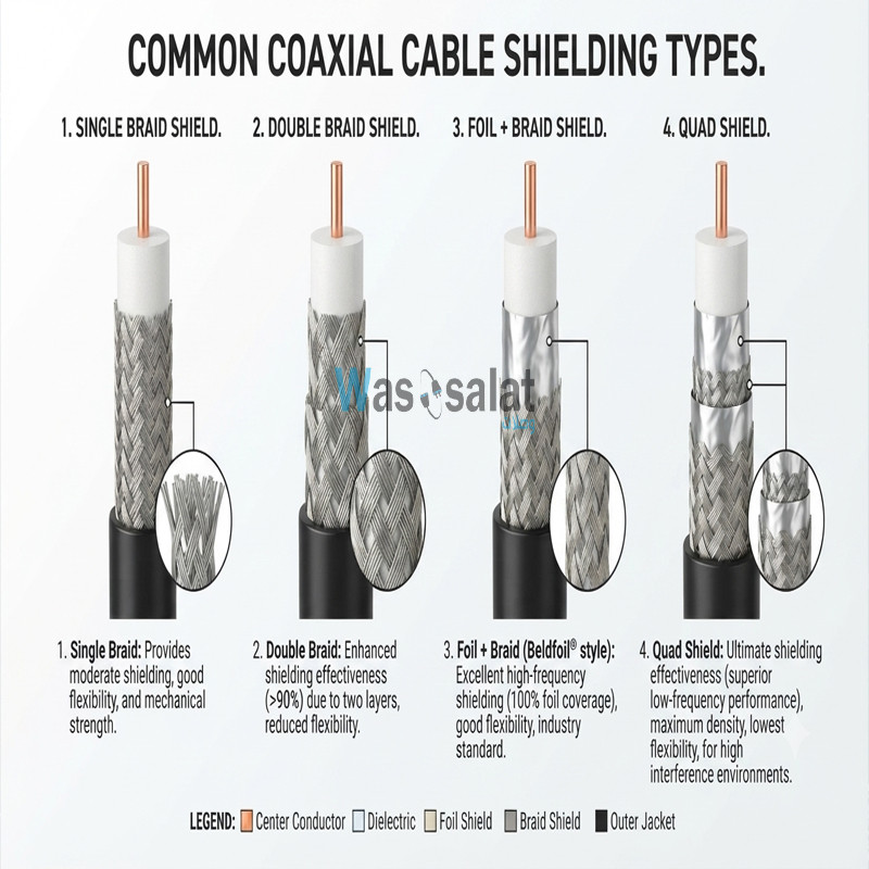 Shielding Types in Coaxial Cables: Complete GuideRead more
This comprehensive guide explains everything you need to know about shielding types—from single shield to quad...
-
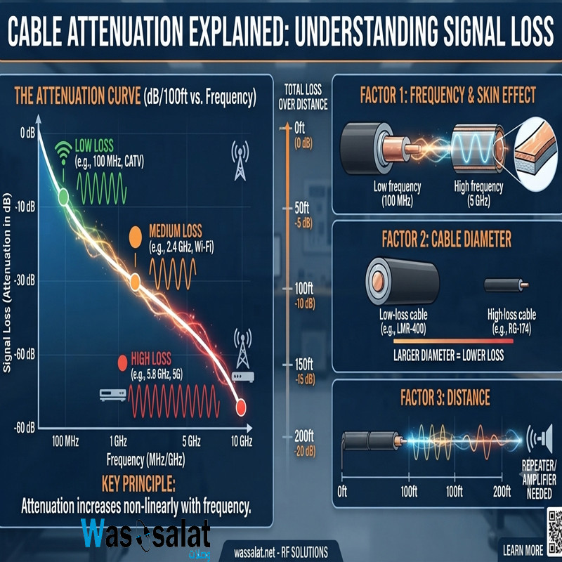 Cable Attenuation Explained: Understanding Signal LossRead more
This comprehensive guide explains everything you need to know about cable attenuation—what it is, what causes it, how...
-
 Outdoor Coaxial Cable: Complete Guide & Selection TipsRead more
Choose the right outdoor coaxial cable for your installation. Compare TZC-500/32 vs TZC-500/97, learn about PE...
-
 LMR-400 vs RG58: Which Coaxial Cable Should You Choose?Read more
Compare LMR-400 vs RG58 coaxial cables. Learn the differences in signal loss, construction, flexibility, and...
-
 Coax Cable Connectors: Complete Guide to F-Type, BNC, N-Type, SMARead more
Learn about coaxial cable connectors—F-Type, BNC, N-Type, SMA, TNC, and UHF. Compare impedances, frequencies, and...
Leave a comment