
This comprehensive guide covers everything you need to know about waterproof coaxial cables—from understanding water...
Testing Coaxial Cable: The Complete Guide
Testing Coaxial Cable: The Complete Guide
Published by Wassalat Technical Team
You've installed your coaxial cable, terminated the connectors, and secured everything in place. But how do you know it's working properly?
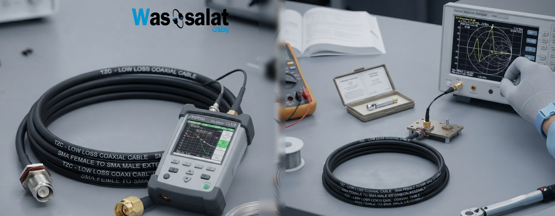
This comprehensive guide covers everything you need to know about testing coaxial cable—from simple continuity checks to advanced signal quality measurements. Whether you're a professional installer or a DIY enthusiast, proper testing ensures reliable performance.
? Table of Contents
Why Test Coaxial Cable?
Testing your coaxial cable installation is essential for several reasons:
1. Verify Installation Quality
Ensure the cable is intact, connectors are properly terminated, and the signal path is clear.
2. Identify Problems Early
Catch issues before they cause service interruptions or signal degradation.
3. Document Baseline Performance
Establish a baseline for future troubleshooting and system validation.
4. Comply with Standards
Professional installations often require certification to industry standards.
5. Ensure Customer Satisfaction
Deliver reliable, high-quality performance that meets expectations.
? Key Insight: It's much easier to test and fix problems during installation than to troubleshoot after equipment is connected and operating. Always test before connecting to equipment!
Testing Tools Overview
Tool Comparison
| Tool | What It Measures | Cost | Skill Level |
|---|---|---|---|
| Multimeter | Continuity, Resistance | $ | Beginner |
| Cable Tester | Continuity, Shorts, Opens | $ | Beginner |
| Signal Meter | Signal Level, Quality | $$ | Intermediate |
| Spectrum Analyzer | Frequency Response, Interference | $$$ | Advanced |
| VNA | VSWR, Return Loss, Impedance | $$$$ | Advanced |
| TDR | Cable Length, Fault Location | $$$$ | Advanced |
Recommended Tools by Application
| Application | Recommended Tools |
|---|---|
| DIY Home Installation | Multimeter or Basic Cable Tester |
| TV/Satellite Installation | Signal Meter, Multimeter |
| Professional Installation | Signal Meter, Spectrum Analyzer, Cable Tester |
| RF/Wireless Installation | VNA, TDR, Spectrum Analyzer |
Continuity Testing
Continuity testing verifies that the cable is electrically intact and has no shorts or opens.
How to Test Continuity with a Multimeter
- Set multimeter to resistance (Ohms) or continuity mode
- Test the center conductor – Connect one probe to each end of the center conductor. Expect < 1 ohm for short cables.
- Test the shield – Connect one probe to each end of the shield. Expect < 1 ohm.
- Test for shorts – Connect one probe to the center conductor and the other to the shield at the same end. Expect no continuity (open circuit).
Continuity Test Results
| Result | Meaning | Solution |
|---|---|---|
| Center to Center: 0Ω | Good continuity | ✔️ Pass |
| Center to Center: Open | Broken center conductor | Replace cable or re-terminate |
| Shield to Shield: 0Ω | Good continuity | ✔️ Pass |
| Shield to Shield: Open | Broken shield | Replace cable or re-terminate |
| Center to Shield: Continuity | Short circuit | Check termination, replace damaged cable |
⚠️ Important: A continuity test only confirms the cable is not broken. It does NOT confirm good signal quality or impedance matching. Always perform additional tests for signal quality.
Signal Level Testing
Signal level testing measures the strength of the signal at the receiving end of the cable.
How to Test Signal Level
- Connect a signal meter to the cable end
- Set to the correct frequency or channel
- Read the signal level in dBmV (for TV) or dBm (for RF)
- Compare to acceptable levels
Signal Level Standards
| Application | Acceptable Range | Ideal Level |
|---|---|---|
| Cable TV (Analog) | 0 to +15 dBmV | +5 to +10 dBmV |
| Cable TV (Digital) | -15 to +15 dBmV | 0 to +10 dBmV |
| Satellite TV | -65 to -25 dBm | -50 to -30 dBm |
| Broadband Internet | -15 to +15 dBmV | 0 to +10 dBmV |
Using a TV/Receiver Signal Menu
Most modern TVs and satellite receivers have a built-in signal meter:
- ? TV Menu → Settings → Signal Information
- ? Satellite Receiver → Settings → Signal Strength/Quality
- ? Cable Modem → 192.168.100.1 → Signal Levels
Signal Loss Testing
Signal loss testing measures how much the signal attenuates as it travels through the cable.
How to Test Signal Loss
- Measure signal level at the source (transmitter end)
- Measure signal level at the destination (receiver end)
- Calculate the difference = Source Level - Destination Level
- Compare to expected loss for the cable type and length
Acceptable Loss Limits
| Application | Maximum Total Loss | Loss per 100 ft (RG6) |
|---|---|---|
| Cable TV (1 GHz) | 8-10 dB | 8.5 dB |
| Satellite TV (2 GHz) | 6-8 dB | 12-15 dB |
| Broadband Internet | 10 dB | 8.5 dB |
? Tip: If your loss exceeds acceptable limits, consider:
- Using a lower-loss cable (e.g., RG11 instead of RG6)
- Shortening the cable run
- Adding a signal amplifier
- Removing unnecessary splitters or connectors
VSWR Testing
VSWR (Voltage Standing Wave Ratio) measures how much signal is reflected back from the cable or antenna. A perfect match is 1:1.
Understanding VSWR
| VSWR | % Reflected Power | Quality |
|---|---|---|
| 1.0:1 | 0% | Perfect |
| 1.2:1 | 1% | Excellent |
| 1.5:1 | 4% | Good |
| 2.0:1 | 11% | Acceptable |
| 3.0:1 | 25% | Poor |
How to Test VSWR
- Connect a VNA or SWR meter to the cable or antenna
- Set the frequency to your operating frequency
- Read the VSWR value
- Compare to acceptable levels
Common Causes of High VSWR
- ❌ Impedance mismatch – 50Ω cable connected to 75Ω equipment
- ❌ Damaged cable – Kinks, cuts, or bends
- ❌ Poor termination – Loose or damaged connectors
- ❌ Wrong connector type – Mixing 50Ω and 75Ω connectors
- ❌ Damaged antenna – Broken or corroded
Interference Testing
Interference testing identifies external signals that may be affecting your cable's performance.
How to Test for Interference
- Use a spectrum analyzer connected to the cable
- Scan the frequency range of your application
- Look for unexpected signals (spikes or noise)
- Identify the source of interference if found
Common Interference Sources
| Source | Frequency | Solution |
|---|---|---|
| WiFi 2.4 GHz | 2.4 GHz | Use quad-shield cable, maintain distance |
| Cellular 4G/5G | 700-2600 MHz | Use quad-shield cable, filtering |
| Power Lines | 50/60 Hz | Maintain separation distance |
| Microwave Ovens | 2.45 GHz | Use quad-shield cable |
| Fluorescent Lights | Wideband | Use quad-shield cable, maintain distance |
Interpreting Results
Pass/Fail Criteria
| Test | Pass | Fail |
|---|---|---|
| Continuity (Center) | < 1 Ω | Open Circuit |
| Continuity (Shield) | < 1 Ω | Open Circuit |
| Shorts (C to S) | No Continuity | Continuity |
| Signal Level (TV) | > 0 dBmV | < 0 dBmV |
| Signal Level (Satellite) | > 80% Quality | < 60% Quality |
| VSWR | < 1.5:1 | > 2.0:1 |
| Interference | None visible | Interference present |
When to Replace a Cable
- ? Continuity failure – Broken center or shield
- ? Short circuit – Center touching shield
- ? High VSWR – > 2.0:1
- ? Excessive signal loss – More than 50% above expected
- ? Water ingress – Visible moisture or corrosion
- ? Physical damage – Kinks, cuts, or crushed sections
Frequently Asked Questions (FAQ)
1. How do I test coaxial cable without a tester?
Use a multimeter to check continuity. You can also connect the cable to a known working device (TV, modem) and check for signal.
2. What is a good VSWR for coaxial cable?
A VSWR of 1.5:1 or lower is considered good. VSWR below 1.2:1 is excellent.
3. How do I measure signal loss in coaxial cable?
Measure signal level at both ends and calculate the difference. Use a signal meter or spectrum analyzer.
4. What is the maximum acceptable signal loss?
For TV, maximum loss is 8-10 dB. For satellite, 6-8 dB. For broadband internet, 10 dB.
5. Can a multimeter test coax cable?
Yes, a multimeter can test continuity and shorts. It cannot test signal quality, VSWR, or impedance.
6. How do I test for interference?
Use a spectrum analyzer connected to the cable. Look for unexpected signals in your frequency band.
7. What is TDR testing?
TDR (Time Domain Reflectometry) sends a pulse down the cable and measures reflections to locate faults and measure cable length.
8. How often should I test coaxial cable?
Test after installation and during troubleshooting. Also test if you suspect damage, water ingress, or performance degradation.
9. What causes signal loss in coaxial cable?
Signal loss is caused by conductor resistance, dielectric absorption, skin effect, leakage, and connector loss.
10. Can I test coax with a tone generator?
Tone generators are used for cable identification, not signal quality testing. Use a proper cable tester for signal quality.
? Related Articles
- Complete Guide to Coaxial Cables
- Cable Attenuation Explained
- Installing Coaxial Cable
- Coaxial Cable Connectors
? Need Cable Testing Tools?
We stock professional cable testers, signal meters, and testing accessories. Ensure your installations work perfectly.
Last Updated: July 2026
© 2026 Wassalat. All rights reserved.
Posted in:
Coaxial Cables
Related posts
-
 Complete Guide to Coaxial Cables
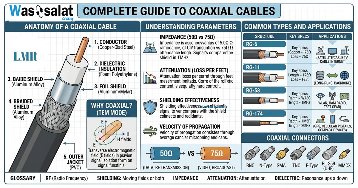
Everything you need to know about RG-6, LMR-400, impedance, connectors & troubleshooting.Read more
Complete Guide to Coaxial Cables
Everything you need to know about RG-6, LMR-400, impedance, connectors & troubleshooting.Read more -
 50 Ohm vs 75 Ohm Coaxial Cables: What's the Difference?
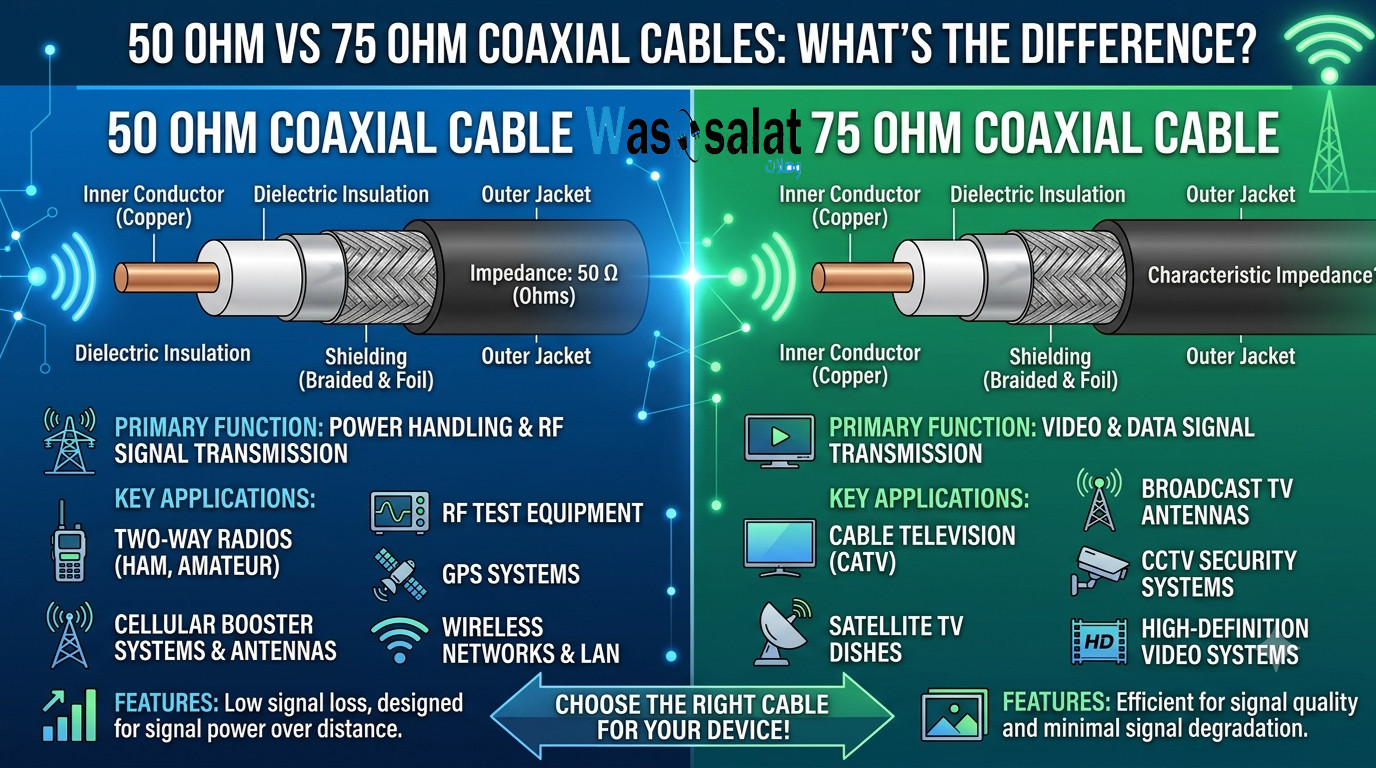
Learn the key differences between 50Ω and 75Ω coaxial cables. Find out which impedance you need for WiFi, TV, CCTV,...Read more
50 Ohm vs 75 Ohm Coaxial Cables: What's the Difference?
Learn the key differences between 50Ω and 75Ω coaxial cables. Find out which impedance you need for WiFi, TV, CCTV,...Read more -
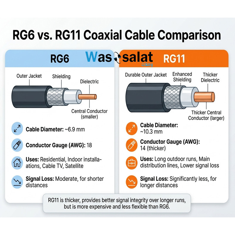 RG6 vs RG11 Coaxial Cables: Which One Do You Need?
Compare RG6 and RG11 coaxial cables. Learn the differences in performance, distance, cost, and when to use each for...Read more
RG6 vs RG11 Coaxial Cables: Which One Do You Need?
Compare RG6 and RG11 coaxial cables. Learn the differences in performance, distance, cost, and when to use each for...Read more -
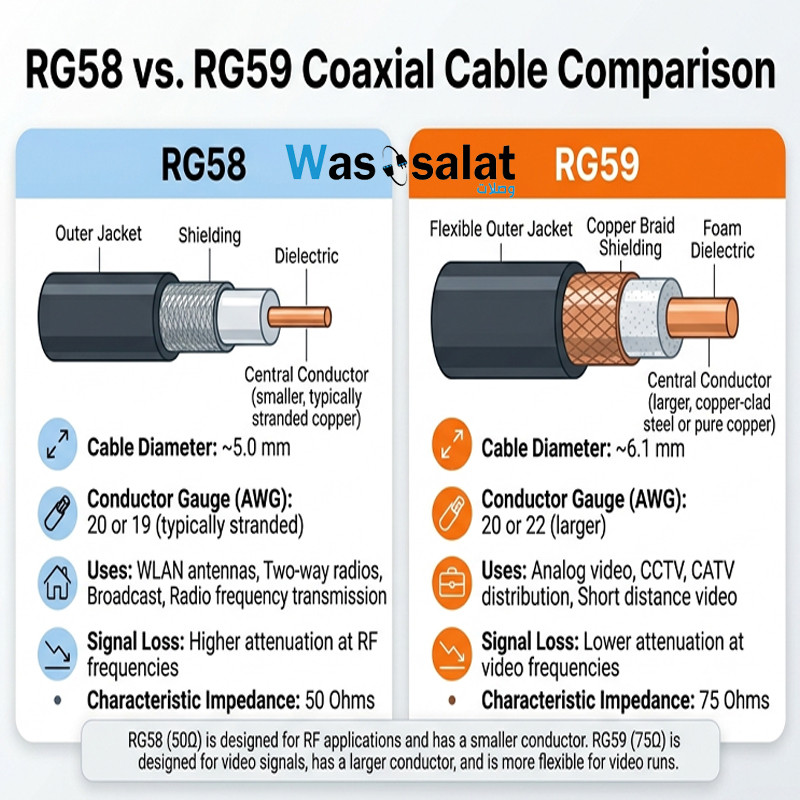 RG58 vs RG59 Coaxial Cables: What's the Difference?
Compare RG58 and RG59 coaxial cables. Learn the critical impedance difference, applications for RF vs video, and...Read more
RG58 vs RG59 Coaxial Cables: What's the Difference?
Compare RG58 and RG59 coaxial cables. Learn the critical impedance difference, applications for RF vs video, and...Read more -
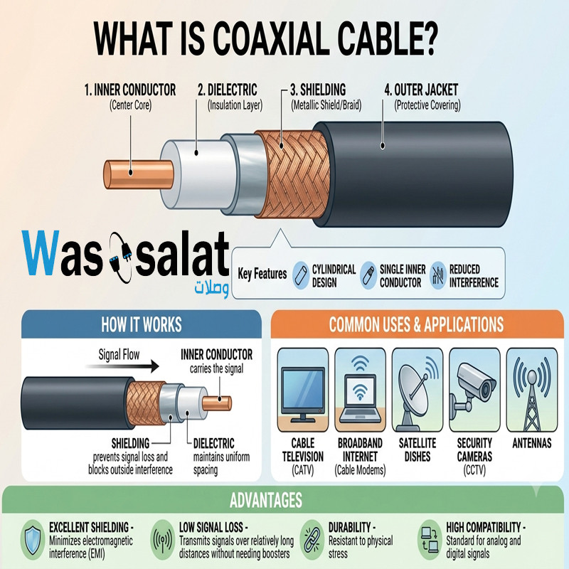 What Is a Coaxial Cable? The Complete Beginner's Guide
Learn what coaxial cables are, how they work, their construction, types, and applications. The beginner's guide to...Read more
What Is a Coaxial Cable? The Complete Beginner's Guide
Learn what coaxial cables are, how they work, their construction, types, and applications. The beginner's guide to...Read more
Latest posts
-
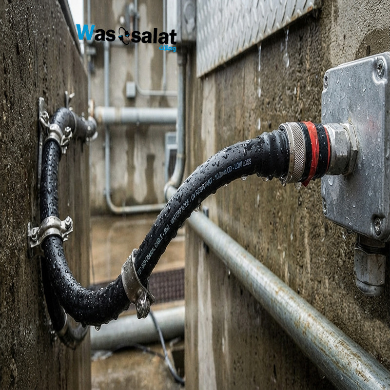 Waterproof Coaxial Cable: The Complete GuideRead more
 -
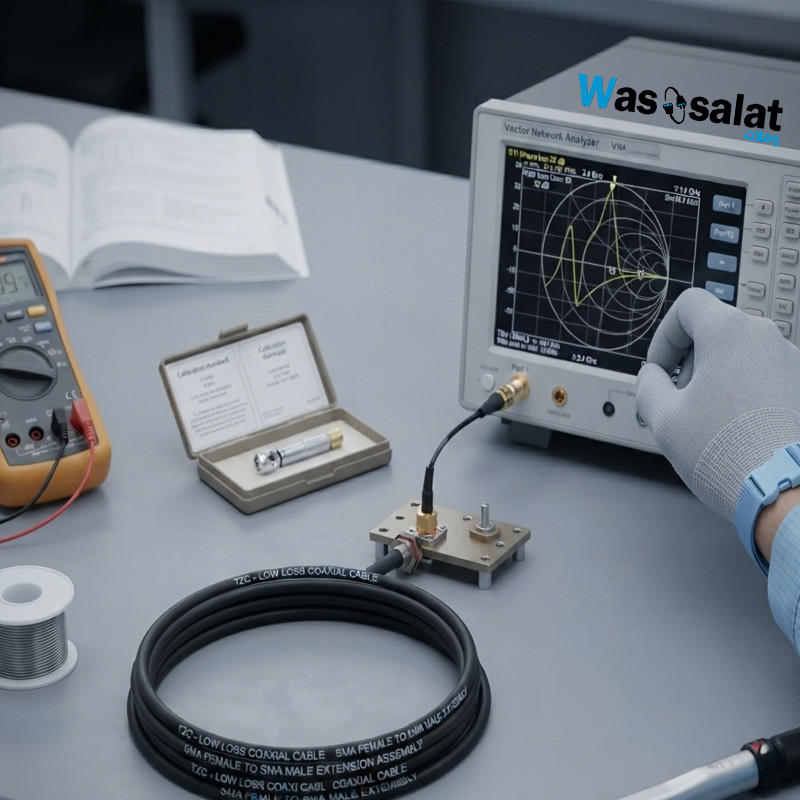 Testing Coaxial Cable: The Complete GuideRead more
This comprehensive guide covers everything you need to know about testing coaxial cable—from simple continuity checks...
-
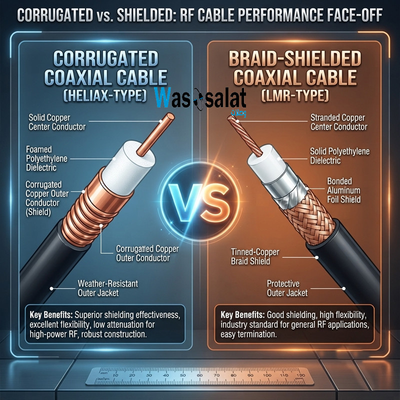 Corrugated Coaxial Cable vs Shielded Coaxial Cable: Complete ComparisonRead more
This comprehensive guide compares both technologies—explaining the differences in construction, performance,...
-
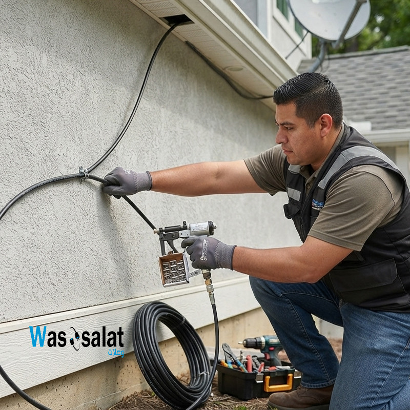 Installing Coaxial Cable: The Complete GuideRead more
This comprehensive guide compares double shield and quad shield coaxial cables—explaining the differences in...
-
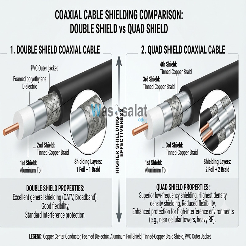 Double Shield vs Quad Shield: Which Coaxial Cable Should You Choose?Read more
This comprehensive guide compares double shield and quad shield coaxial cables—explaining the differences in...
-
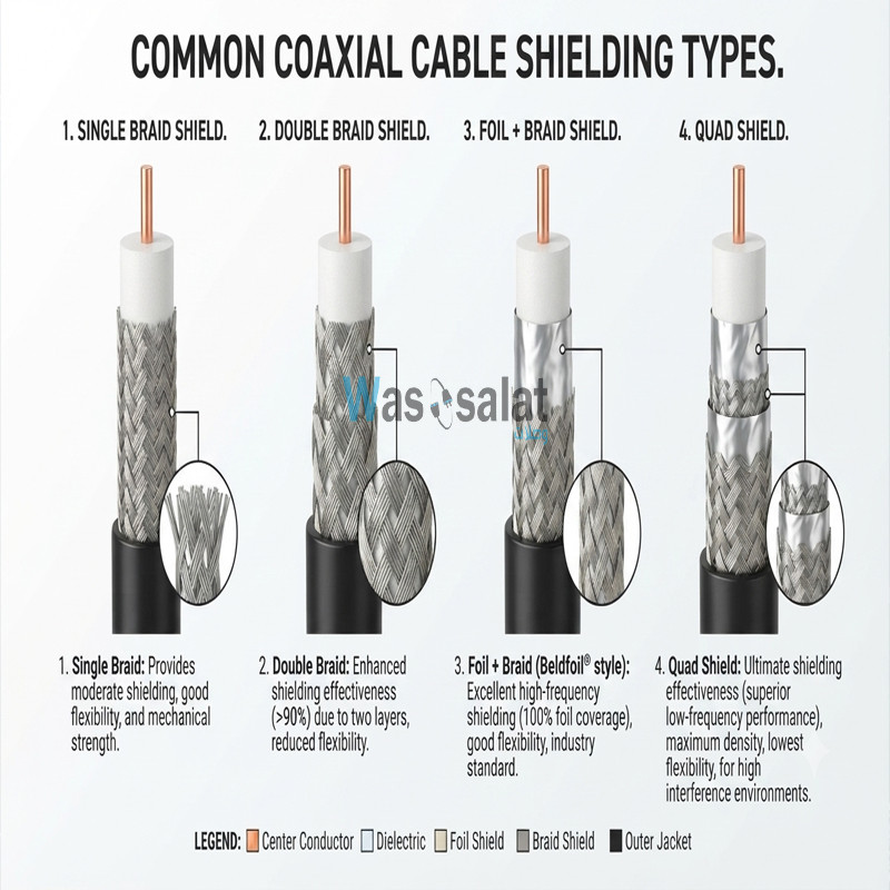 Shielding Types in Coaxial Cables: Complete GuideRead more
This comprehensive guide explains everything you need to know about shielding types—from single shield to quad...
-
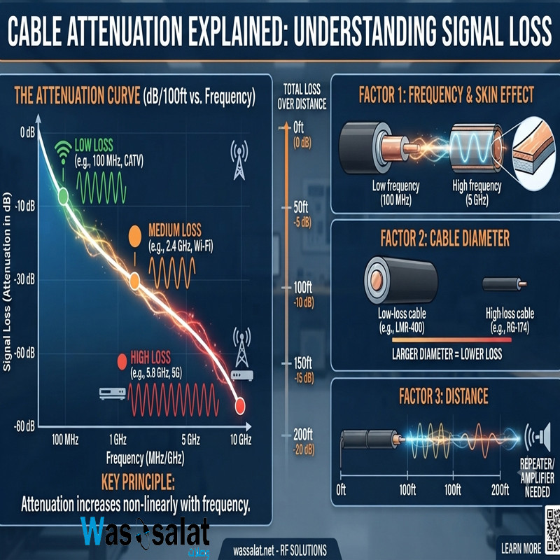 Cable Attenuation Explained: Understanding Signal LossRead more
This comprehensive guide explains everything you need to know about cable attenuation—what it is, what causes it, how...
-
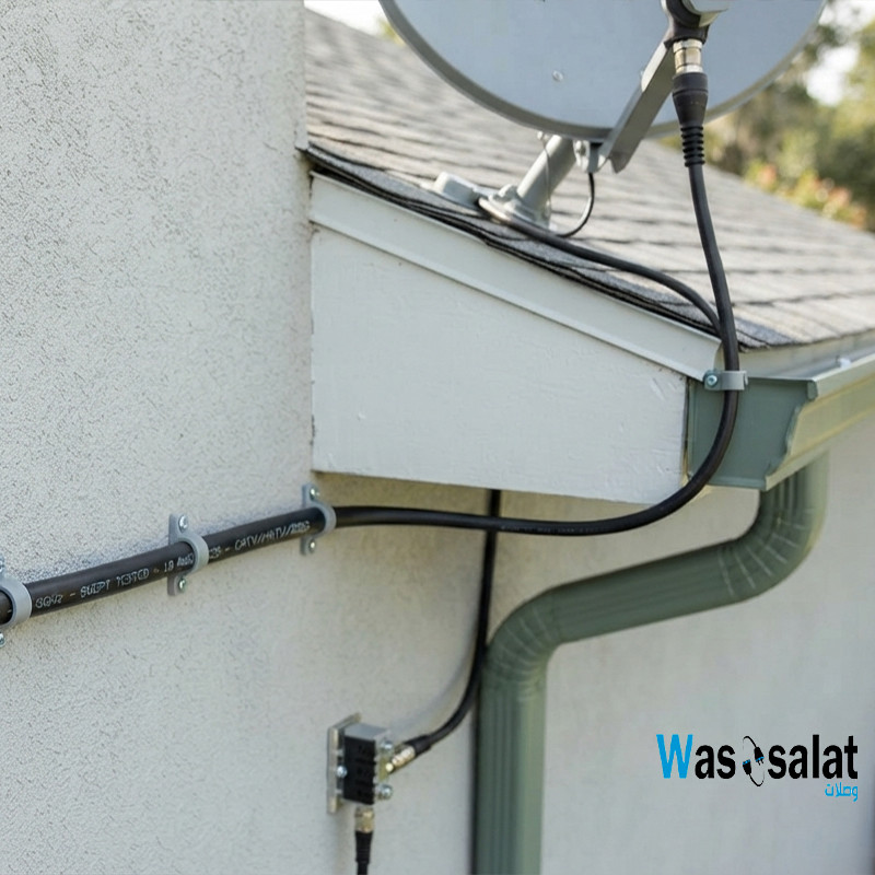 Outdoor Coaxial Cable: Complete Guide & Selection TipsRead more
Choose the right outdoor coaxial cable for your installation. Compare TZC-500/32 vs TZC-500/97, learn about PE...
-
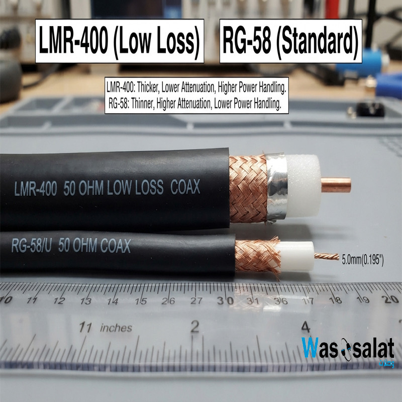 LMR-400 vs RG58: Which Coaxial Cable Should You Choose?Read more
Compare LMR-400 vs RG58 coaxial cables. Learn the differences in signal loss, construction, flexibility, and...
-
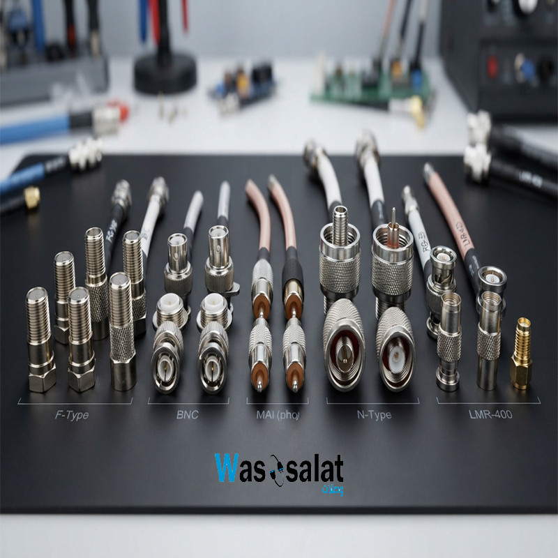 Coax Cable Connectors: Complete Guide to F-Type, BNC, N-Type, SMARead more
Learn about coaxial cable connectors—F-Type, BNC, N-Type, SMA, TNC, and UHF. Compare impedances, frequencies, and...
Leave a comment